Friday, September 18, 2015

The Chicken and the Armadillo

One of the first Texas jokes my then middle school daughter picked up was:

Why did the chicken cross the road?

To show the armadillo it could be done!

The number of armadillo frisbees on Texas highways is proof that for those poor creatures, it's just not in the cards. I'm told that when startled by an oncoming car, armadillos jump straight up in the air to perfect bumper height. Unfortunate.

I tell that story to show you this:


Notice anything different?

It's facing the other direction!

I'm afraid that I did not have a camera crew on hand to capture the first drive, but I needed to show myself that it could be done. It was once around the block and back in the garage. Didn't want to alarm the local traffic patrol with a car that's basically naked in front. 

The good news is that the low hanging battery cage didn't scrape at the end of the driveway. The regen braking will take some getting used to and I suspect that I'll be fiddling with the throttle mapping to get it just right, but my first impression is that it's a smooth and civilized ride.

Now for jumping up to bumper height:

Here is the new configuration for the contactor and precharge relay:


It's considerably more compact than the Better Place contactor module it replaces. I plan to make a cover for it, painted black of course so it disappears.

Pretty as it is, I still don't have the precharge routine figured out - arc welded both this brand new contractor and the one in the back. As long as they are stuck in the closed position, I figured "Why not take it around the block?" And I did, despite the non functional DC/DC converter and ruined contactors. And it was pretty darned satisfying.

We're leaving on a week's vacation tomorrow for a tour of the upper Mid-West with my parents, visiting places that have memories from their childhood. Now I can relax and enjoy the trip knowing that I've at least had one successful spin around the block.

The week after, I'm driving up to Cape Girardeau to participate in the EVCONN that wasn't. Jack Rickard has invited anyone interested to drop by for an open house at his shop. I'll be able to consult with the best and brightest on what I'm doing wrong, and pick up replacement parts while I'm there.

When I get back, we're going to make this armadillo fly!


Disappointment Part Deux

The ink was still wet on my prior posting when Jack Rickard announced the cancellation of EVCCON 2015. Seems the liability insurance bond required for holding an event like this fell through and at this late date that's not recoverable.

Details here.

Jack did offer his shop for an open house that week and since I still have a hotel room reserved, I think I'll drive up for at least a couple of days to hang out with my EV pals.


Thursday, September 17, 2015

Disappointment

No pictures - not a lot to say. The Porsche won't be ready to take to EVCCON this year. The replacement contactor and precharge resistor/relay arrived late Tuesday. Spent all day Wednesday crafting a new mount for them in place of the arc-welded ones. That was all fine.

Also fine was the charger: it started up exactly as I had planned and loaded in 35 amp hours of energy, then terminated exactly as it was supposed to. The charge controller seems to be losing its configuration parameters when powered off, but otherwise ok.

I did notice that the 12 volt battery was dropping in voltage even though the DC/DC converter seemed to be running - at least the fan was spinning. When I plugged the laptop in to the controller, nothing, nada, pushing up daisies, pining for the fjords. You get it, casters up. I know it was working when installed, don't have an explanation for this one, but wasted the better part of today trying to get it to wake up.

So it's an extended game of Whack-A-Mole, and I only have one day left to get it rolling on its own power. With some regret, I decided to cancel the truck and trailer rental and go to EVCCON as a civilian this year. I will enjoy hanging out with my EV pals, and have a much better sorted vehicle to take next year.

Even so, it's a bummer ...

Monday, September 14, 2015

Small Fixes While Waiting for the Big Fix

The replacement contactor, precharge resistor and relay are on the UPS truck scheduled for delivery by end of day tomorrow. In the mean time, I've tackled some of the smaller chores that needed to be done to get everything ready for the road.

I installed the tail light assemblies on Saturday. They use a tar-like windshield seal instead of gaskets. The windshield seal comes in a roll with a wax paper separator between the 3/8" thick seal. It's pretty messy, but should be water tight. Once cleaned up, it looks as if it just came from the factory.

I spent most of Sunday afternoon working on the hood release cable, only to realize that it was frayed with a halo of strands making it impossible to snake through behind the carpet. It's replacement has also been ordered and should arrive midweek as well.

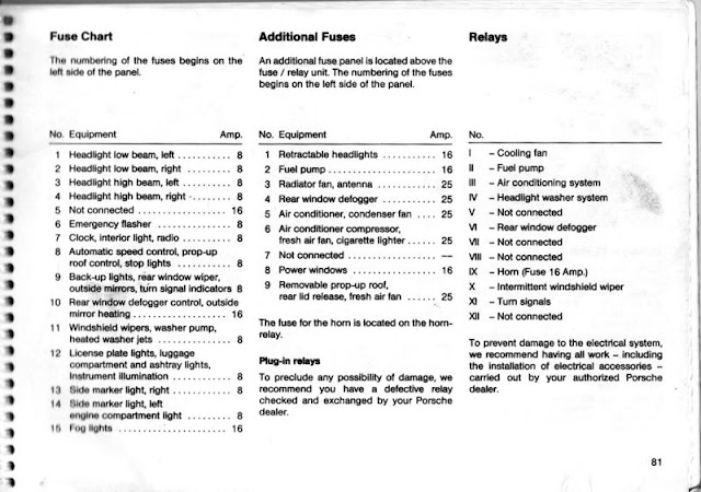
The tail lights don't light yet, I'm thinking they need the front running lights and turn signals to complete the circuits. I did solve the mystery of the pop up headlights, though, and probably cured the intermittent nature of the power windows. All it took was crawling into a heroically contorted position on my back under the dashboard. Oh, and finding the correct fuse reference charts online. These look like they came from the owners manual. How did we ever get by without Google? 


Now that I know where to look for the retractable headlight fuse, here's what I found:

It's obviously blown, and the fact that it's an 8 amp fuse in a 16 amp circuit might have something to do with that. Checking the rest of the fuses lead to the realization that they were placed pretty randomly. These ceramic euro fuses are the same as the ones used in the VW Beetle, not surprising given the close ties between VW and Porsche back in the day. I picked up an assortment of the fuses and used most of them.

Some were just questionable. The new one's on the left - what's with the narrow fuse link in the old one?
Others were just scary, but creative. Kind of like putting a penny behind an old fashioned screw-in house fuse (if you're old enough to remember such things), someone improvised this replacement fuse by cutting a piece of wire and splaying the uninsulated wire strands over the fuse ends. It certainly would complete the circuit, but defeat the purpose for the fuse. This one was in the power windows slot which calls for a 16 amp fuse. Easy to see why the power windows only worked occasionally. Now they'll actually go up and down twice in a row and then do it again!
Almost 30 years of wear and tear have taken their toll on a lot of the convenience items. It looks like I'll be replacing all the interior light fixtures - they're all the same - and only one out of four lights up and dimly at that.

Tomorrow, more clean up and Wednesday we'll hope to get this thing on the road!

Thursday, September 10, 2015

For Want of a Nail

So near yet so far.

Yesterday was focused on completing the battery pack area in the rear under the hatch. There was a good bit of fabrication involved and I'm really pleased with the results. 

First, the Nissan master disconnect/fuse unit was installed on the left of the pack.
 Then the DC/DC Converter control box with fuse and AVC2 charge control on the right. The red circular device on the edge is an inertia switch to shut off power in the event of an impact. The little red thing sticking out behind it is a switch for the enable signal. I connected the normally closed terminal of the AVC2 relay to the enable line of the GEVCU to prevent driving off with the charge cord attached. Turning off the enable switch will prevent the car from running. It's a rudimentary security feature, and our little secret. 

There is more hiding beneath this shelf: the mid-pack contactor and a terminal strip to connect the J1772 charging port with the charger and controller. The spaghetti will be out of sight down here.


Viewed as a whole, I think the battery bay looks tidy and businesslike.


With all the cabling in place, it was time to power up. Just as I turned the switch, there was a clap of thunder outside and I couldn't help thinking ...


All the pumps were pumping and pack voltage read correctly when turned on, then showed zero when off. Charging started up when the J1772 was plugged in. All good. So I went off for a late celebratory supper with plans to finalize the configuration in the morning and maybe take the first spin around the block.

Alas, was not to be. I calibrated the throttle and power cycled the GEVCU, but noticed that my multimeter was still showing full pack voltage when the system was turned off. Not good. Last night it was zero, now full pack voltage and dropping slowly, eventually getting into the millivolts range. It occurred to me that I was watching the capacitors in the DMOC drain which must mean that the contactors were still closed. Something awry with my precharge routine? I pulled the rear contactor and it checked fine.

Then I pulled the Better Place contactor module and found that the contactors were both locked in the closed position. Contacts welded shut! The GEVCU manual has a full chapter on precharge considerations, and my setup worked as it should last night. What happened?

Here's the culprit: sorry it's out of focus, but you can see the chunk of insulation that's missing. This is the common +12 volt connection for both contactors and the precharge relay. The GEVCU manages the startup sequence by opening first the precharge relay ground line, then the main contactor's ground after the capacitors have reached pack voltage, avoiding the inrush surge current that welds the contacts closed. What changed?
The yellow circle highlights the connection for the wire above. This particular wire was a bit too short to connect with the +12 volt terminals at the left of the box, so I connected it to the normal input side of the diode. Good +12v there, but a rather awkward placement - notice that it passes over the top of the output terminal on the charger side of the diode. I must have nicked the wire when I installed it, and then the bare wire made contact with the charger power output screw. When I plugged in the J1772, power passed through that screw to the contactors without the GEVCU managing the connection. Result: inrush current and welded contacts. I've ordered a fresh contactor, precharge relay and resistor. UPS should deliver them early next week, so all is not lost. Unless, of course, there is collateral damage to the GEVCU, but won't know that until later.

For want of a nail the shoe was lost
For want of a shoe the horse was lost.
For want of a horse the rider was lost.
For want of a rider the message was lost.
For want of a message the battle was lost.
For want of a battle the kingdom was lost.
And all for the want of a horseshoe nail.


Monday, September 7, 2015

Circuit Box

Three very long days in my 90+ degree garage have put the project ever closer to it's first test drive. 


That tangle of wiring at the back of the inverter is finished save for one wire to the reverse switch. 


It looks like total chaos, but there is a method to the madness. The relays (clockwise from the upper left) control the 12 volt switched ignition, power steering pump, heat exchanger fan, and charger. Almost invisible above the charger relay is a dual power diode that enables what I hope is a clever way of automating the charge process. I can't test that until the rear wiring is done (tomorrow, if all goes well), but in theory, it's very cunning. I have been able to test the power brake vacuum pump, power steering pump, and coolant pumps, and all are spot on! I do plan to put a cover on the circuit box so it looks neat and tidy.

The vacuum pump has its own relay and wiring jumble. Yesterday I solved the mystery of how and where to hook up the vacuum lines to get the air conditioning flap to operate. Once it did, it moved an impressive amount of air, and will need to be somehow integrated with the aftermarket AC compressor. That's for another day.
The 12 volt battery feeds an eighty amp breaker that serves all the EV circuitry and provides a single shut-off point. The 50 amp fuse on the left protects the power steering pump. With the battery pack cabling ahead tomorrow, along with the remainder of the charging support, we are closing in on a first test drive. Keep checking in ...

Friday, September 4, 2015

Wiring the Motor Bay

Spent the day routing wires and organizing the split loom to keep things neat and organized. Started by wiring the power steering pump and aggregating with the cooling pump wiring for a single loom into the circuit box.


After cutting the high voltage cable to size, I crimped on the lugs and installed the contactor module. 

The GEVCU is mounted to the rear of the inverter and excess cable is coiled on the coupler housing below it. Other wiring is tagged and ready to be connected to the GEVCU harness.


The charge controller is mounted to the front of the inverter and all connected to the charger.


The fan wiring is consolidated with the charger and throttle wiring, then routed to the back of the inverter where it will be fed with all the other connections into the circuit box.

Thursday, September 3, 2015

Meanwhile ...

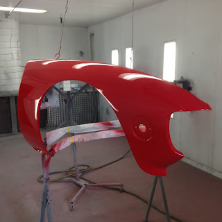
Robert has been painting up a storm. These all look great, and I'm afraid the rest of the car will need the same treatment down the road a bit.


Robert mentioned that I really should get the headlight covers painted as well so they match. He's right, of course, so I pulled them off the car and took them over. The car will look fantastic!

Robert also finished out the top cover for the coupler housing, so I picked that up and spent nearly all morning installing it. It's in a very awkward place with no room to swing a wrench, so four bolts took way too long. It had to be done now because the GEVCU will be  mounted over it and it will be even more obscured with all the cabling that goes along.

The afternoon was spent on an equally fussy project, fabricating and installing the charge port. Again, working in the hatch behind the former gas filler is an exercise in contortion, but the payoff is a really pretty piece of bling.


Along with those two major projects, I finished installing the GEVCU and Charge Controller now that the paint has dried on the mount box, and started gathering the under hood wiring into split looms for connection to the GEVCU harness in the circuit box.  

Tuesday, September 1, 2015

Building Better Boxes

A couple of nights ago I woke up at 2:30am with a brilliant idea that came to me in a dream. OK, maybe not so brilliant, but gives you some idea about what I've been dreaming about lately. It actually made sense the next morning, and had nothing to do with Dilithium Crystals, Gigawatt Transformers, or Ancient Aliens.

I have not been happy with the contactor box being in the rear of the car with the battery pack. I had already run high voltage wires through the passenger cabin along with the control wiring, which made me nervous. It just wasn't right.

I had wasted the better part of two days trying to find a space in the motor bay, but they were either too low and subject to water splash, or too precariously fragile. 

Here's the dream: (In the voice of Charlton Heston) Build ye a box around the inverter, and behold thy contactor module may be affixed thereto. Yea, verily I did proceed to do just that, using pressure treated exterior 5/8" plywood that was left over from the evTD project. Some scrap aluminum angle and a treaded rod to hold it all in place, and that's the box. With some T-nuts and three bolts, it's a comfortable fit in the space between the inverter and the coolant catch tanks with all the plumbing below.

The contactor module was included with the Better Place battery pack and contains the positive and negative contactors along with the precharge resistor and control relay, all nicely integrated. It has the connections for the high voltage wiring from the battery pack and output connections for the inverter.

The front of the box will mount the charger controller and the GEVCU system controller will mount on the back. The GEVCU manages a whole range of car functions in addition to the motor speed control, and needs a way to connect a bunch of wires in some orderly way.

I had spent hours laying on my back under the dashboard in a contortionist pose that would would make Cirque de Soleil proud. I found and removed what Porsche calls the "Digital Motor Electronic Control Unit". Just as I suspected, once it was disconnected, the basket of snakes under the hood slithered off. All that messy wiring was there to feed sensor information about the gas motor to the ECU so it could fiddle the timing and fuel injection. After hours of searching, I finally found the switched 12 volt wire, a single wire among the seven bundled into the cruise control harness. With all of that gone, the motor bay is a much neater place.

So now the electric motor needs the same sort of inputs and outputs, so a circuit box was built and mounted on the top rear of the inverter. Four relays and twenty six terminal connections will be centrally housed here with all wiring entering and exiting through the open back. I think I'll put a hinged lid on it for easy access later.

A coat of black paint will make the whole apparatus disappear, then I can mount the components and wire everything up. That should basically finish the under-hood activity and we'll move on to the back. Tomorrow is another day ...