Monday, March 23, 2015

Dodged a Bullet ... YES!

It took about a week, but I can happily say that there appears to be no damage to the affected battery cells! To review:

The chain welded itself to the positive terminal of cell 21 and the negative terminal of cell 26, causing a dead short and fully discharging the six cells in between.


Here's what it looked like after the chain was pried off. 


The other side of the battery pack looks pretty toasty with the melted plastic and burnt off terminal bolt heads. In fact, the underlying cells were only slightly discharged compared to the other unaffected cells. It took a set of vice-grips to get the bolts loose, but once loose, they spun out easily and there was no damage to the terminals!

The chain took a beating and I think what happened was the chain welded across the six cells made the pack into a resistive arc welder. At a pretty high discharge rate the sparks were plenty spectacular, but didn't actually do all that much damage. It's good to know that these batteries can take this level of abuse with no thermal runaway.

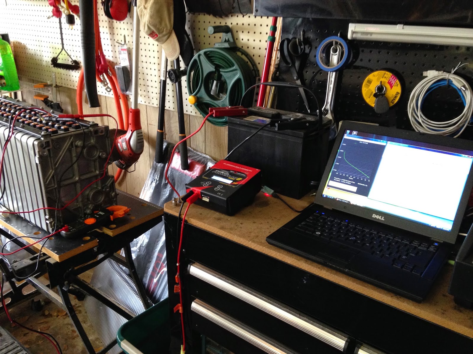
I described the recovery process in the last post, but after running the affected cells through multiple charge/discharge cycles I've learned a thing or two about these cells. The voltage increase during a charge is more linear than with LiFePo4 cells from CALB or Thundersky, but the capacity increase is heavily back-end loaded. From roughly 3.0 volts to 4.0 volts the cell gains 30-35 amp hours of capacity. Then between 4.0 and 4.2 volts including the constant voltage stage, an additional 25-30 aH of capacity is loaded. So these cells want to be charged to 4.2 volts.

It's pretty doubtful that the TC Charger that I have will charge beyond its 389 volt max and if it did, it would be at the ragged edge of it's capabilities. Very recently, Jack Rickard, Mark Weisheimer and the team at EVTV have done the programming work to make the OEM grade 420 volt Lear chargers used in the Chevy Volt available and configurable for folks like me. I've ordered one, and that has triggered a rethinking of the configuration strategy for the Porsche.

The Lear charger is liquid cooled, which accounts for the smaller size. After considering running coolant hoses from the front of the car to the back or setting up a separate charger cooling system in the back with its own radiator, pump, and catch tank, I decided to move the charger to the front and use the same plumbing as the motor and inverter. The batteries that were such a problem to fit under the hood will now occupy the back seat area. The DC/DC converter and 12 volt battery will also relocate to the front so there is some weight transfer to partially offset the battery move. That rear jump seat was pretty unusable anyway and this approach will make for a much cleaner installation.

Once all the dust settles, I'll be putting the TC Charger up for sale on eBay along with the Sachs clutch pack and any other leftover bits. If you're interested, please get in touch.


Tuesday, March 17, 2015

Dodged a Bullet ... Maybe?

Quick update ... I set up the battery lab on the workbench again and hoisted the damaged battery module onto the workmate, this time with nylon strap. I bought a small variable DC power supply to bring each cell up gently to around 3 volts so the PowerLab8 would recognize them, then did a charge to 4 volts. After a rest period to make sure it would hold the charge, discharge to 2.75 volts, the bottom balance target.


The first cell seems to have recovered ok, the second cell has been charged and is now in the discharge phase. Looks ok so far, with four more to do after that.

One disconcerting sign is that the capacity seems low at around 35 amp hours. The cells are supposed to be rated for ~60aH. I ran a good cell through the process and got the same roughly 35 aH, so at least it's consistent. It could be a measurement issue, or maybe a result of charging to only 4 volts. We'll tackle that after we're sure that we have recovered from the damage. Stay tuned ...

UPDATE: I went back and watched Jack Rickard's video from March 14, 2014 (yes, that's a whole year ago) and it looks like I'm actually doing pretty well on the amp hour counts. He recorded about 27 aH at 4.0 volts and noted that most of the capacity increase occurred between 4.0 volts and 4.2 volts with about a quarter of the capacity coming in the constant voltage stage of the charge. He got a full 60 aH with that technique and recommends 4.2 volts as the termination point with an extended constant voltage stage down to about 3 amps. Now the question is: will my 4kW charger with it's nominal 389v (4.05v/cell) upper limit stretch to the 403v needed for 4.2v times 96 cells?

Friday, March 13, 2015

One Step Forward, Two Steps Back

First the good news:

Last post I showed the EV West interference fit coupler for the Siemens motor. It arrived this week and I took it over to Pro Automotive for Robert Juarez to have a look at it. We discussed grinding the rivets off of the clutch disk and using the center section to mate with the splines on the drive shaft. Keith pointed out that if we bolt the clutch center section directly to the flange of the coupler, we effectively eliminate the spring effect, so why not attach the spline directly? 


Given that the coupler from the Siemens motor to the E-Gear drive on the Transit Connect is a straight splined tube with no shock absorbing capability, why not?


On the left you see that Robert has removed the spline from the old clutch disk and fashioned a round mounting plate from sheet steel. On the right is the spline in position on the mounting plate. Welding the spline to the plate will be  stronger than the press fit in the original clutch. Dave, the machinist next door, will drill and tap the plate and coupler to make sure that everything is precisely centered, trued, and balanced. So work on the coupler is moving along nicely. Once we are able to mount the motor, we can get on with fitting everything under the hood.


Now the bad news:

VERY SIGNIFICANT GOOF BY ME!

I had mounted a chain to one of the batty pack modules to get it off the workbench in preparation for Robert to pick it up and take it to the shop to install in the Porsche. That was fine until last night my wife was bringing in groceries and knocked it off and it shorted the exposed terminals on the front. I know better than to use a metal chain, but as Hillary Clinton said "it was a matter of convenience."

The good news is no explosion or fire, but lots of sparks as the chain welded itself to some of the terminals. It looks like it's pretty much toast.

The plan is to insulate the remaining exposed terminals, pry or cut off the welded chain links, and assess the damage. With any luck, some of the batteries will be usable. Fingers crossed!

It looks like these batteries are available from a couple of sources, so all is not lost. It will drive the cost up, but at this point I'm too far in to let that get in the way. Chalk it up to expensive lesson learned.


Tuesday, March 3, 2015

Back to Work

It seems like forever since there's been any progress to report. Life happens and you deal with it as it comes, but now things are starting to free up and I'm very excited to see the project move forward.

Robert Juarez has been working on the accessory mounts: planning, positioning, and fabricating. It is truly a three dimensional jigsaw puzzle in the motor compartment and we don't have everything figured out yet, but we're making great strides.

First off, Robert made cardboard mock-ups of the Siemens motor, DMOC inverter, and battery blocks of four modules each. 


One dependency that has finally been nailed down is the method of mating the motor to the driveshaft. I had originally planned a conventional approach using a flywheel, clutch, and pressure plate, but delays in getting the adapter plate and coupler built led me to look around for an alternative. I found a very persuasive argument for going with a clutchless coupler on the Porsche 944 build blog of a fellow from Alberta, Canada and rather than repeat it here, follow this link and check it out for yourself.

Given that the primary goal of this project is to replace my Nissan Leaf, the numbers look good. The Leaf uses a single speed reduction gear with a final drive ratio of around 7.94:1. In second gear, the Porsche 924S has a final drive ratio of 8.26:1, just a bit shorter than the Leaf. The Porsche should be quicker than the Leaf from a standing start with the slightly lower gear ratio, lighter weight, and higher motor power (134 hp for the Siemens vs. 107 for the Leaf). Driving will be much like an automatic: start in second gear and just leave it there.

The other benefit of going clutchless is that the coupler is a good four inches shorter than would be possible with a full clutch setup, and that four inches makes a big difference under the hood. 

The thing that makes this possible is a sweat fit coupler blank for the Siemens motor developed by EV West. The coupler is heated up and positioned on the splined motor shaft and as it cools, it shrinks to a very tight fit. The center hub of a Porsche clutch disk with the friction surfaces removed provides the spline fit for the transaxle shaft, and a spacer in between accommodates the pilot shaft. Drill and tap the coupler and this sandwich will connect the motor shaft to the transaxle shaft.


In order to keep the power steering, we're using a Toyota MR2 electric power steering pump. It is a very popular item for drag racers and hot rods as well as electric conversions. As a result, they are getting a little hard to find, but wrecking yards do still have used ones. It has an integrated fluid reservoir, so makes a tidy installation. Robert found a perfect place for it on the passenger side of the motor bay and fabricated a custom mount. 


Directly behind the power steering pump, the niche that formerly held the starter battery now contains the main contactors and precharge resistor directly from the Better Place  battery pack along with the power brake vacuum pump. The vacuum pump is a Ford unit designed for the Transit Connect electric delivery vehicle. The Ford Transit Connect is also the source for the Siemens motor and Azure Dynamics DMOC 645 inverter, so the vacuum pump is in familiar territory.


On the other side of the motor bay, Robert has mounted the Benling Air Conditioning compressor. We've kept all of the other A/C components in place, so we should be able to tolerate Texas summer heat. Like the power steering pump, I'll need to have custom hoses built to match the fittings on these non-Porsche parts.


Moving around to the rear of the car, the battery structure is nearly complete. This will hold two full banks of sixteen battery modules and a small four module set along with the charger, mid-pack fuse, and maintenance disconnect. The outer skin for the battery box will be fabricated from sheet aluminum and fully caulked to seal out moisture, then finished off with black truck bed liner. Also to mount in the back is the 12 volt auxiliary battery and DC/DC converter. Those items will fit in the side storage areas beside the battery box. 

So things are starting to take shape. We are still trying to figure out where to put the remaining batteries and the cooling system components, but once the motor and inverter are mounted, those things should fall into place.